
How does picosecond laser microprocessing limit heat-affected zones?

How Does Picosecond Laser Microprocessing Limit Heat-Affected Zones?
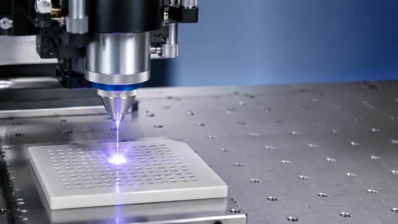
Picosecond laser microprocessing limits heat-affected zones (HAZ) by depositing energy into a small volume of material faster than substantial heat can spread into the surrounding substrate. The pulse duration is measured in picoseconds—trillionths of a second—while the pulse peak power can be high enough to initiate rapid ablation, plasma formation, and material ejection. In practical terms, the process seeks to remove material before the thermal load develops into the wider melting, resolidification, oxidation, or microcracking associated with longer-pulse laser machining.
For technical evaluators, “minimal HAZ” should not be treated as an automatic property of an ultrashort-pulse source. It is a measurable process outcome shaped by pulse duration, wavelength, fluence, repetition rate, beam delivery, scan strategy, material condition, and the required geometry. A picosecond system can produce exceptionally clean features, but it can also create heat accumulation, recast material, or collateral damage if the process window is poorly chosen.
This distinction matters in semiconductor singulation, medical-device structuring, battery-component processing, precision drilling of ceramics, display manufacturing, thin-film patterning, and machining of carbon-fiber composites. In these applications, the acceptable thermal footprint may be more important than nominal throughput. A small crack network beside a ceramic hole, a delaminated composite edge, or a thermally altered metal surface can compromise the function of an otherwise dimensionally correct part.
The Physical Basis: Energy Arrives Before Heat Can Travel Far
The central advantage of picosecond processing is temporal confinement. With nanosecond laser pulses, energy is generally delivered over a period long enough for heat conduction, melting, vaporization, and molten-pool dynamics to influence adjacent material during the pulse. The resulting machined zone may contain a visible recast layer, altered grain structure, oxide formation, or a broader thermally affected region.
A picosecond pulse is much shorter. Electrons in the target absorb laser energy first; energy transfer to the crystal lattice and broader thermal diffusion occur later. If the incident fluence is above the ablation threshold, material can be removed through rapid phase change, ejection of ionized material, and related non-equilibrium mechanisms before a conventional melt pool has time to dominate the interaction. The remaining substrate still receives some heat, but the depth and lateral spread of that heat are typically far more limited.
This is often described as “cold ablation,” although that phrase can be misleading. The interaction zone is not cold: temperatures and energy densities at the focal point can be extreme. The useful engineering claim is narrower: thermal damage outside the intended removal zone can be reduced when the process is appropriately optimized.
Thermal diffusion length provides a useful conceptual check. It scales approximately with the square root of thermal diffusivity multiplied by interaction time. Reducing the pulse duration from nanoseconds to picoseconds sharply reduces the distance that heat can diffuse during energy deposition. Yet the relevant time is not only the pulse width. At high pulse repetition rates, the interval between pulses, beam overlap, and local cooling conditions become equally important.
Why a Short Pulse Alone Does Not Guarantee a Small HAZ
A common evaluation error is to compare laser sources only by pulse duration. A 10 ps source is not inherently safer for a sensitive part than a 100 ps source if the shorter-pulse system is operated at excessive fluence, uses heavy pulse overlap, or repeatedly scans the same region before it can cool. Conversely, a somewhat longer picosecond pulse may deliver an acceptable result when the beam path, energy density, and debris management are controlled.
The effective process window lies between two undesirable conditions. Below the removal threshold, energy is absorbed inefficiently and can accumulate as local heating without stable ablation. Far above the useful fluence range, the process may produce a larger plasma plume, stronger shock effects, redeposition, and unnecessary thermal loading. The preferred window is material- and geometry-specific, which is why parameter transfer between suppliers or laboratories should be treated cautiously.
Repetition rate deserves particular scrutiny. Higher repetition rates can increase average power and apparent productivity, but they reduce the cooling time between pulses. On thin metals, thermally conductive substrates, coated stacks, or heat-sensitive polymers, local heat accumulation can become visible even when each individual pulse is ultrashort. Scan speed, hatch spacing, burst mode, and the sequence of passes must therefore be evaluated together rather than as isolated settings.
Parameters that materially affect HAZ control
Material Behavior Changes the Definition of “Clean”
Metals usually reveal excessive heat input through recast, resolidified droplets, oxide discoloration, burr formation, or subsurface microstructural alteration. For stainless steels, titanium alloys, copper alloys, and nickel-based materials, the visual appearance of a cut is not sufficient evidence of a controlled HAZ. Metallographic cross-sections, surface analysis where function requires it, and dimensional inspection are more reliable than visual acceptance alone.
Semiconductors and thin films introduce different risks. A process may produce a narrow kerf while creating chipping, latent cracking, dielectric damage, or changes in electrically active layers. In wafer-related work, edge damage and particle contamination may be as consequential as heat-affected depth. Process qualification should be aligned with device architecture, downstream cleaning, and any applicable semiconductor manufacturing requirements rather than based solely on optical microscopy.
Ceramics benefit from the reduced bulk heating associated with picosecond laser microprocessing, but their brittleness means that shock-induced cracking and local tensile stress still require attention. Alumina, zirconia, silicon nitride, glass, and technical ceramics may respond differently depending on porosity, grain structure, surface finish, and thickness. Hole drilling is particularly demanding because debris evacuation deteriorates with depth, and repeated pulses can alter the local thermal environment.
For carbon-fiber-reinforced polymers and related composites, the target is not merely a narrow kerf. The process must avoid matrix recession, exposed or fractured fibers, fiber pull-out, interlaminar damage, and an unacceptable change to the resin near the edge. Different constituents absorb and conduct energy differently, so a parameter set that looks favorable on a flat coupon may not transfer directly to formed components or variable layups.
How to Benchmark HAZ Instead of Relying on Demonstration Samples
Supplier demonstrations often emphasize a single clean feature under controlled conditions. That is useful for establishing feasibility, but it does not establish process capability. A robust benchmark should replicate the relevant material lot, thickness, coating state, geometry, fixturing, and production duty cycle as closely as practical. If the part will be processed after forming, heat treatment, plating, or additive manufacture, those conditions should be represented in the trial.
The acceptance plan should define HAZ in functional terms. Depending on the component, this may include maximum altered-layer depth, absence of visible recast, edge chipping limits, roughness, taper, debris level, crack criteria, electrical performance, bondability, corrosion behavior, or fatigue-relevant surface condition. Not every project needs every measurement, but vague language such as “no thermal damage” creates disputes because it cannot be inspected consistently.
Several established standards can support the measurement plan without serving as a universal laser-processing specification. ASTM E3 provides guidance for metallographic specimen preparation, ASTM E407 addresses microetching of metals and alloys, and ASTM E384 covers microindentation hardness testing where hardness mapping is relevant. ISO 4287 and ISO 25178 are commonly referenced for profile and areal surface texture parameters. ISO 11553 addresses laser processing machine safety, while laser safety classification and workstation controls also need review under the applicable regulatory framework. The correct combination depends on the product, sector, and contractual acceptance criteria.
A credible qualification package usually includes
- Cross-sectional evidence from representative features, including challenging corners, deep holes, or start-stop locations.
- A documented parameter window rather than one nominal recipe, with identified limits for energy, overlap, focus, and scanning conditions.
- Inspection-method repeatability: magnification, section orientation, sampling locations, and the definition used for HAZ measurement.
- Evidence from an extended run or a production-representative duty cycle to reveal thermal drift, contamination, and optic-condition effects.
- Traceability for material condition, optical setup, assist gas or extraction configuration, and software version where those variables affect output.
The Often-Overlooked Role of Beam Delivery and Debris Control
HAZ performance can be undermined outside the laser source itself. Focus drift caused by imperfect height control, field distortion in scanner optics, beam pointing instability, or contamination on protective windows changes the delivered fluence at the workpiece. In a narrow process window, these changes can move the operation from clean ablation toward melting or incomplete removal without an obvious machine alarm.
Debris extraction also deserves engineering attention. Ablated particles and plume products can shield subsequent pulses, redeposit on surrounding surfaces, contaminate optics, or create secondary thermal effects in confined geometries. Airflow, vacuum extraction, assist-gas selection, and fixture design should be tested as part of process development. This is especially relevant in high-value optical, electronic, vacuum-compatible, and medical applications where loose particulate is a separate quality risk.
Machine vision and optical inspection can close part of this gap by monitoring alignment, feature position, debris, and gross edge defects. However, in-process imaging does not replace destructive sectioning or functional testing during qualification. Surface appearance remains a weak proxy for subsurface damage.
A Decision Framework for Technical Evaluators
Picosecond laser microprocessing is most compelling when conventional mechanical, chemical, or longer-pulse thermal methods create unacceptable damage or require expensive post-processing. It is not automatically the lowest-cost route for high-volume material removal. The trade-off is often between cleaner quality at the feature level and the capital, process-development, motion-control, and inspection discipline required to sustain that quality.
A sound evaluation begins with the failure mode that must be prevented. Is the concern a metallurgical HAZ, a burr, a crack, coating delamination, fiber damage, particle generation, or a device-performance change? The answer determines the material characterization method and whether picosecond processing offers a meaningful advantage. Only after that should the team compare source specifications, average power, wavelengths, scanner architecture, automation, and throughput.
This is where multidisciplinary benchmarking is useful. G-AIT examines industrial laser processing alongside machine vision, advanced materials, additive manufacturing, and vacuum or cryogenic engineering because the true process risk often sits at the interface between disciplines. A laser recipe cannot be assessed independently of material traceability, inspection capability, contamination control, safety obligations, and the standards used to define acceptance.
The practical question is therefore not whether picosecond pulses eliminate heat. They do not. The relevant question is whether the complete process can confine thermal and structural change below the functional limit of the component, repeatedly and with evidence that survives technical review. That requires representative trials, explicit measurement criteria, and a parameter window that accounts for normal production variation.
Related News
How to verify part consistency before choosing a 3D printing OEM
Choosing a 3D printing OEM? Learn how to verify part consistency with repeat-build trials, validated inspections, and traceability checks before committing to production.
How does a rigid cryogenic transfer line handle thermal contraction?
Learn how a rigid cryogenic transfer line manages thermal contraction with bends, bellows, and guided supports. Discover key design checks for safe, reliable cryogenic performance.

How much does edge vision deployment cost beyond the hardware?
Understand edge vision deployment cost beyond hardware, from data and integration to security and support. Uncover hidden expenses and build a smarter lifecycle budget before you scale.
How does the purity of sputtering targets affect thin-film quality?
Discover how sputtering targets affect thin-film quality. Learn to assess purity, identify harmful impurities, and choose specifications that improve coating performance.
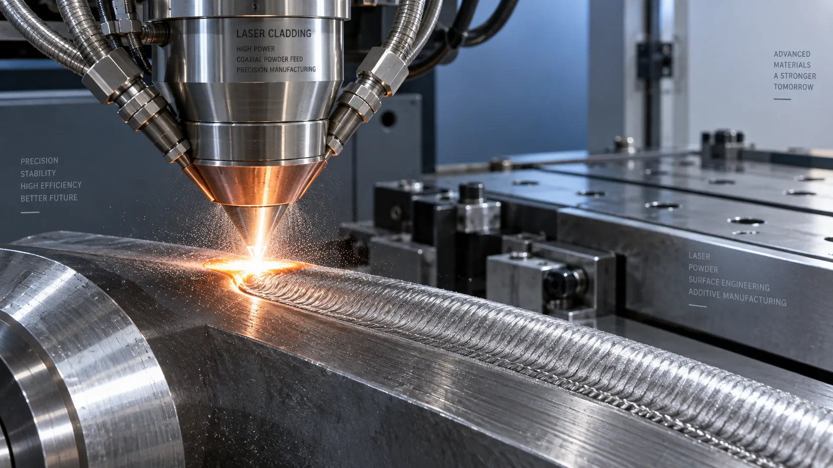
How high power laser cladding systems control substrate dilution
Discover how high power laser cladding systems control substrate dilution through beam shaping, material feed, and thermal management to deliver reliable bonds and coating performance.

How to check HS codes for customs compliance in international logistics
Strengthen international logistics customs compliance: learn how to verify HS codes, check official tariffs, and document classifications to reduce costly shipment delays.
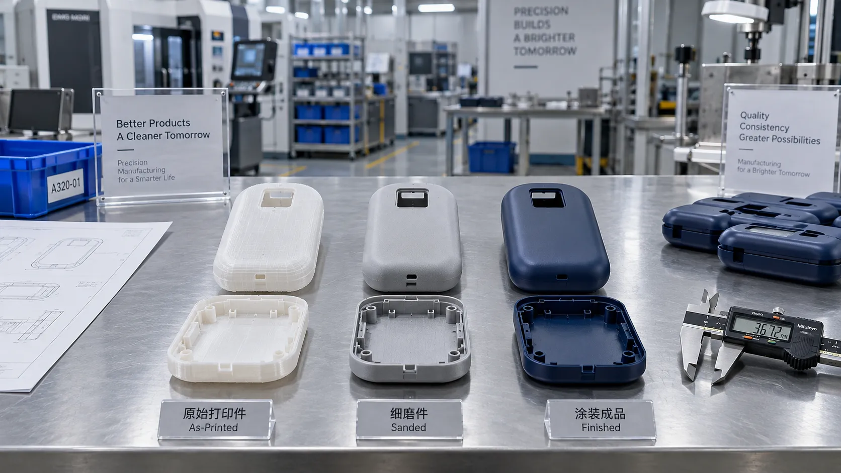
Choosing a 3D Printing Service for Consumer Products: Finish, Fit, and Cost
Compare 3d printing consumer good services by finish, fit, materials, and total cost. Learn how to choose a reliable supplier and avoid costly defects before ordering.
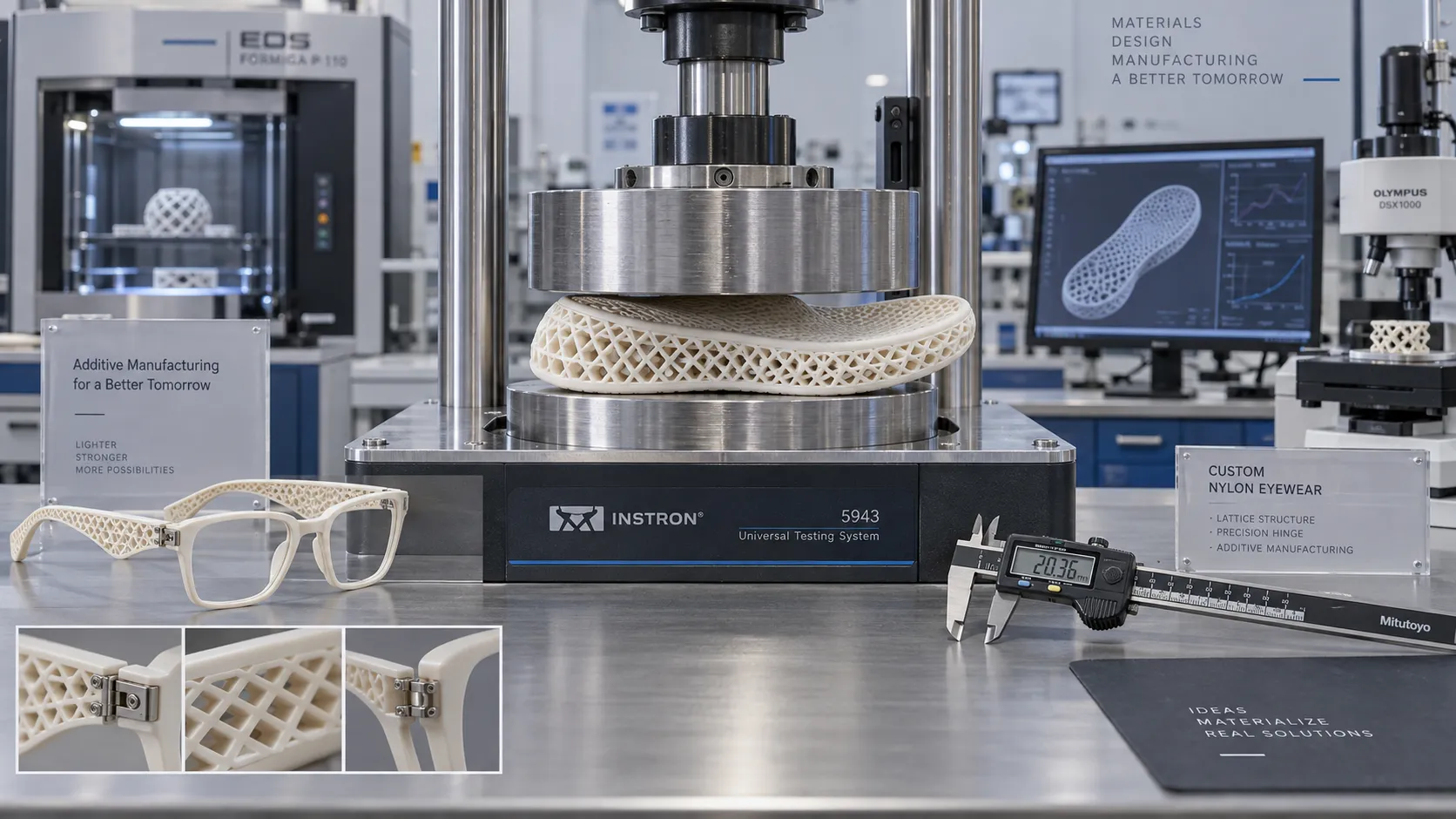
Which Consumer Goods Can Be 3D Printed, and What Are the Practical Limits?
Explore 3d printing consumer goods, from custom eyewear to replacement parts. Discover practical limits on materials, safety, and costs to make smarter production decisions.
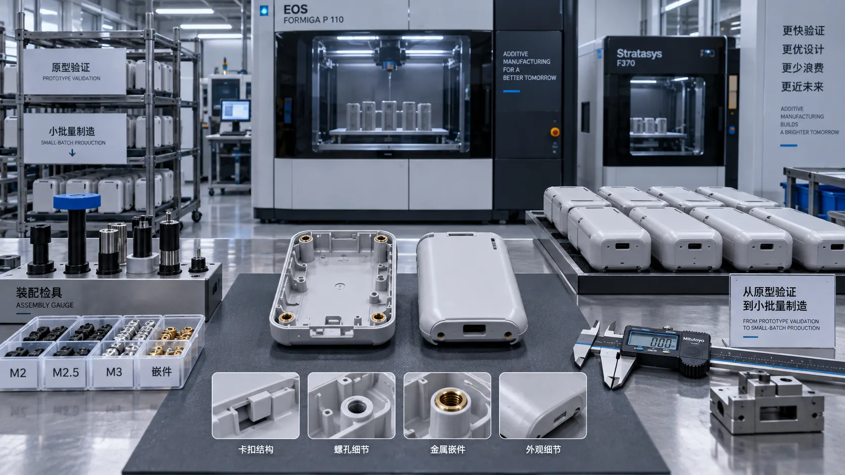
From Prototype to Small Batch: Applying 3D Printing to Consumer Goods
Explore 3d printing in consumer goods: learn how to move from prototype to small-batch production with practical guidance on materials, quality validation, and cost control.
Related News
- 00
0000-00
How to verify part consistency before choosing a 3D printing OEM - 00
0000-00
How does a rigid cryogenic transfer line handle thermal contraction? - 00
0000-00
How much does edge vision deployment cost beyond the hardware? - 00
0000-00
How does the purity of sputtering targets affect thin-film quality? - 00
0000-00
How high power laser cladding systems control substrate dilution
Dr. Hideo Tanaka
Weekly Insights
Stay ahead with our curated technology reports delivered every Monday.