
Specification preparation for power modules: defining key ratings

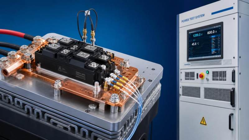
Specification Preparation for Power Modules: Defining Key Ratings Before Supplier Selection
A power-module specification is not a rewritten datasheet request. It is the engineering document that translates a real converter duty cycle into requirements a supplier can quote, test, and stand behind. When that translation is vague, teams often receive modules that appear compliant at nominal conditions but fail the actual application: a laser power supply with repetitive overloads, a vacuum pump drive operating at altitude, an inverter exposed to condensation, or a high-current additive-manufacturing system with insufficient thermal margin.
For technical evaluators, specification preparation for power modules should begin before supplier comparison. The goal is to define the electrical, thermal, insulation, mechanical, control, and lifetime boundaries of the module in measurable terms. A module’s headline voltage and current ratings matter, but they are only part of the decision. In many industrial projects, the decisive issues are switching loss at the intended gate condition, junction-temperature cycling, isolation coordination, cooling-interface quality, and the evidence available for qualification.
This distinction becomes especially relevant in high-performance industrial systems. Multi-kilowatt laser sources, metal 3D printers, machine-vision platforms, cryogenic controls, and vacuum equipment can all impose operating profiles that differ sharply from the smooth, steady conditions assumed in an early concept design. A robust requirement sheet makes those differences visible before procurement locks in a package, topology, or supplier.
Start with the converter duty, not the module catalog
The first useful question is not “Which module current rating do we need?” It is “What electrical and environmental stress will the semiconductor see during its life?” That means documenting the converter topology, DC-link range, load profile, switching frequency, modulation method, operating quadrants, cooling architecture, and fault-clearing strategy.
A module selected for a motor inverter may be unsuitable for a resonant power supply, even when their output power appears similar. Motor drives may require strong short-circuit behavior and tolerate lower switching frequency. A high-frequency industrial power supply may place greater emphasis on switching energy, parasitic inductance, reverse-recovery behavior, and gate-loop stability. In a pulsed laser application, short high-power events can dominate thermal cycling even if average power remains moderate.
The requirement should therefore distinguish between continuous operation, periodic overload, transient events, commissioning conditions, and credible fault conditions. “100 A operating current” has little meaning unless it is tied to waveform, duration, switching conditions, case temperature, and cooling assumptions. The same applies to DC-bus voltage. A nominal bus level is not the design limit; the module must be assessed against the maximum sustained voltage, normal overshoot, abnormal overshoot, and the derating approach used by the system.
Define voltage ratings with margin and insulation coordination in view
The blocking-voltage rating of an IGBT, MOSFET, SiC MOSFET, or diode is a starting point, not a complete voltage specification. The power-stage team should state the highest DC-link voltage, expected switching overshoot, acceptable overshoot margin, and the measurement point used to verify it. Overshoot calculated from a simplified stray-inductance value is useful during design, but it is not a substitute for test evidence from the final laminated busbar, gate driver, snubber arrangement, and physical layout.
For high-speed silicon-carbide modules, this is particularly important. Fast switching can reduce switching loss, but it can also make layout-induced voltage spikes, common-mode noise, and gate-drive sensitivity more visible. A specification that simply asks for “SiC compatibility” leaves too much interpretation to the supplier. It should identify the intended switching-voltage range, target switching speed or loss boundary, permitted dv/dt where relevant, and interface expectations for the gate driver.
Insulation requirements need separate treatment. The module’s isolation voltage is not interchangeable with a system’s insulation-coordination requirement. Technical evaluators should identify working voltage, overvoltage category where applicable, pollution degree, altitude, insulation class, and creepage and clearance constraints at assembly level. IEC 60664-1 is commonly used as a reference point for insulation coordination, while the applicable converter or equipment standard may add its own obligations. For drives and power-electronic systems, IEC 61800 and IEC 62477 families may be relevant depending on the end product and market route.
Current ratings require a thermal interpretation
Continuous collector current or drain current is among the most misread figures in a module datasheet. It may be tied to a stated case temperature, a particular junction-temperature limit, idealized cooling, or package constraints that differ from the proposed assembly. It should never be copied into a system requirement without clarifying those conditions.
A practical specification separates at least four values: normal RMS current, maximum continuous RMS current, repetitive overload current, and non-repetitive fault-related current. It should also describe phase count and waveform. Inverter phase current, DC-link current, and semiconductor current are related but not identical. That distinction matters when comparing modules across topologies or when a procurement document is shared between electrical and mechanical teams.
For diode-containing modules, reverse-recovery characteristics can be as consequential as the forward current rating. In high-frequency applications, recovery charge, recovery softness, and the interaction with the switching device may influence both loss and electromagnetic interference. For SiC MOSFET designs, the body-diode operating behavior and third-quadrant conduction strategy deserve explicit review rather than an assumption that all reverse-conduction modes are equivalent.
Thermal performance is an assembly requirement
Power modules do not operate at “ambient temperature.” They operate at a junction temperature determined by losses and the full thermal path: chip-to-baseplate, baseplate-to-interface material, interface-to-cold plate or heatsink, and coolant or surrounding air. The requirement sheet should name the reference temperature used in calculations. A coolant inlet temperature, a heatsink temperature, and a module case temperature cannot be used interchangeably.
The mechanical details are not secondary. Flatness of the mounting surface, thermal-interface material type and thickness, applied mounting torque or clamping force, surface finish, and cooling-plate flow conditions can materially change thermal performance. A module may meet calculated losses on paper and still run hotter than expected because the cold plate has uneven contact or because the assembly process has inconsistent torque control.
Thermal cycling must be considered separately from maximum junction temperature. A design held near a stable high temperature may face one reliability profile; a design that repeatedly swings through large junction-temperature excursions can face another. The specification should therefore define the expected mission profile: start-stop cycles, power pulses, load changes, coolant temperature variation, and expected service life. If the project requires supplier lifetime evidence, ask what test conditions underpin the claim and whether those conditions are relevant to the intended thermal excursion and on-time profile.
Switching behavior and gate-drive conditions must be specified together
Loss values in a datasheet are conditional. They depend on current, voltage, junction temperature, gate resistance, gate voltage, commutation loop inductance, and often on the test circuit itself. A supplier comparison becomes unreliable when one module is evaluated at a different gate resistance or temperature than another. The specification should request switching-energy curves or characterized values over the relevant range, along with the test conditions used to obtain them.
For IGBT modules, turn-on and turn-off energies, saturation voltage, diode recovery, short-circuit capability, and desaturation-protection compatibility are frequent discussion points. For SiC modules, gate-voltage tolerance, recommended negative gate bias if any, switching-loop inductance limits, Miller behavior, and dv/dt-related insulation stress often deserve more attention. The right choice is not automatically the lowest-loss device. In a noisy industrial enclosure or a long-cable installation, a slightly slower switching strategy may provide a more controllable system.
This is also where evaluator teams should avoid a familiar mistake: treating gate-driver design as a later integration task. The module, driver, busbar, protection thresholds, and EMC approach form one switching system. A good module specification identifies the expected driver interface, auxiliary-emitter or Kelvin-source needs, sensing arrangement, and protection response requirements early enough to prevent an avoidable redesign.
Qualification evidence should match the operating environment
Standards and qualification documents are valuable, but the relevant question is always scope. IEC 60747 provides a broad framework for semiconductor devices, yet equipment compliance usually depends on the complete assembly and its intended use. A power module can have appropriate component documentation while the finished converter still requires separate evaluation for spacing, protective earthing, temperature rise, EMC, functional safety, or environmental exposure.
Specify the evidence required rather than merely asking for “certification.” Depending on the project, that may include datasheets with test conditions, package drawings, material declarations, isolation-test information, reliability reports under controlled access, traceability procedures, change-notification policy, and production-test coverage. If operation includes humidity, conductive dust, vibration, salt-laden air, low pressure, or repeated thermal shock, state those conditions plainly. They cannot be inferred from a standard industrial-temperature range.
This evidence-based approach is consistent with technical benchmarking across advanced manufacturing sectors. At G-AIT, power-electronics evaluation is best treated as part of a wider system-integrity question: how electrical ratings interact with laser sources, motion systems, optical inspection equipment, vacuum infrastructure, or material-processing platforms. The data that matters is not the most impressive catalog figure; it is the figure tied to a verifiable method and a clearly defined boundary condition.
Write acceptance criteria that procurement can actually use
A technically strong requirement is still incomplete if it cannot be used to compare bids consistently. Separate mandatory requirements from preferences and from information requests. For each mandatory rating, identify the acceptance basis: supplier declaration, datasheet condition, calculation, sample test, design review, or qualification record. This avoids the common situation where two suppliers both answer “compliant,” but one is referring to a maximum silicon rating while the other is referring to a validated operating point.
It is worth recording exclusions as well. If a module will be evaluated only with a specified cooling plate, gate driver, and busbar arrangement, say so. If the supplier is expected to support a different assembly, that should be treated as a separate validation condition. Ambiguity at this stage tends to reappear later as disputed thermal limits, unexpected switching behavior, or unclear warranty boundaries.
The most useful power-module specification does not attempt to predict every failure mode. It establishes the ratings, conditions, margins, and proof required to make an informed engineering decision. Before releasing it for supplier engagement, review every current, voltage, temperature, and lifetime statement against the actual mission profile. If a rating cannot be connected to a real operating condition or verification method, it is probably not yet a requirement—it is only an assumption.
Related News

How to verify part consistency before choosing a 3D printing OEM
Choosing a 3D printing OEM? Learn how to verify part consistency with repeat-build trials, validated inspections, and traceability checks before committing to production.
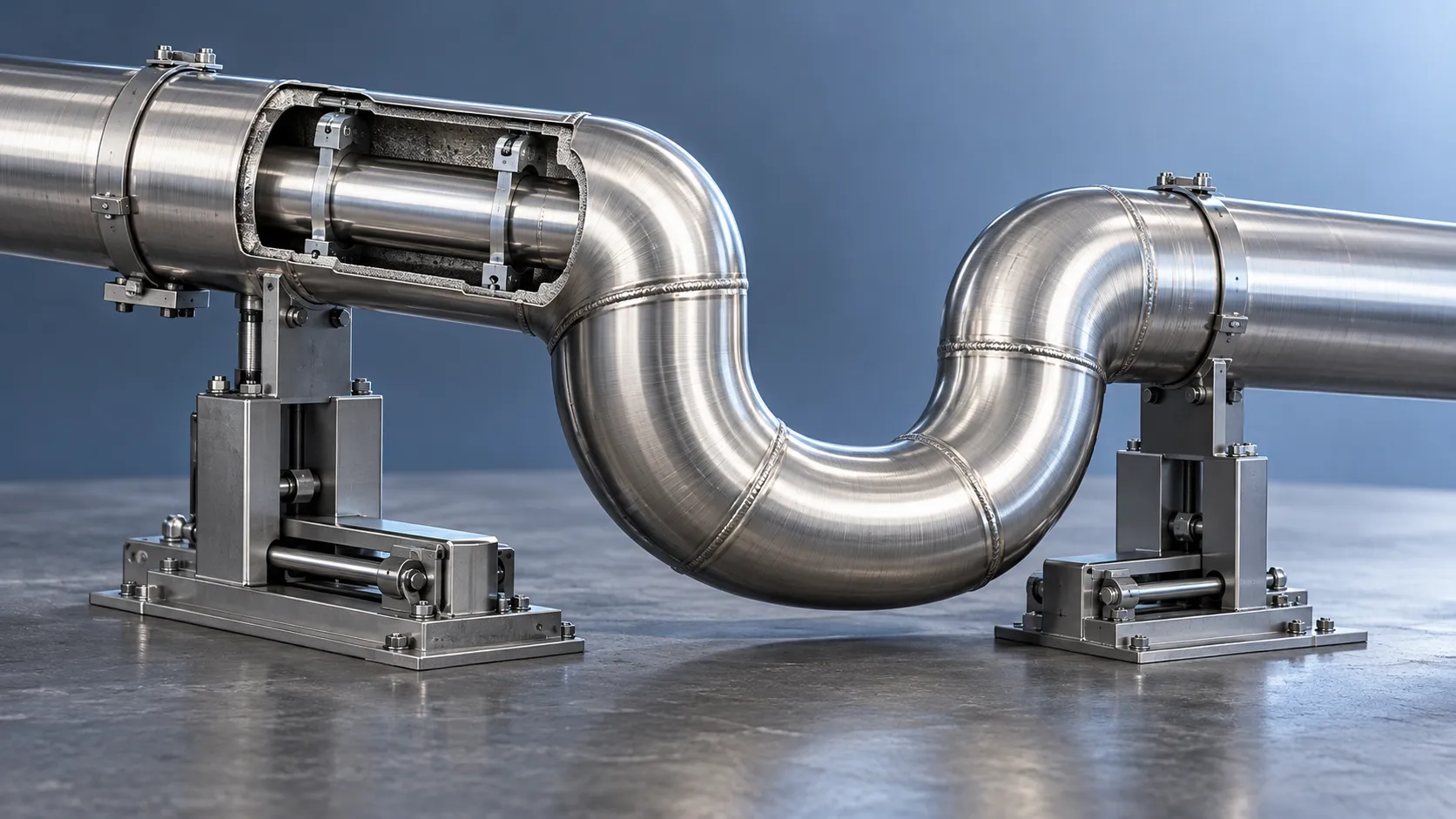
How does a rigid cryogenic transfer line handle thermal contraction?
Learn how a rigid cryogenic transfer line manages thermal contraction with bends, bellows, and guided supports. Discover key design checks for safe, reliable cryogenic performance.

How much does edge vision deployment cost beyond the hardware?
Understand edge vision deployment cost beyond hardware, from data and integration to security and support. Uncover hidden expenses and build a smarter lifecycle budget before you scale.

How does the purity of sputtering targets affect thin-film quality?
Discover how sputtering targets affect thin-film quality. Learn to assess purity, identify harmful impurities, and choose specifications that improve coating performance.

How high power laser cladding systems control substrate dilution
Discover how high power laser cladding systems control substrate dilution through beam shaping, material feed, and thermal management to deliver reliable bonds and coating performance.

How to check HS codes for customs compliance in international logistics
Strengthen international logistics customs compliance: learn how to verify HS codes, check official tariffs, and document classifications to reduce costly shipment delays.
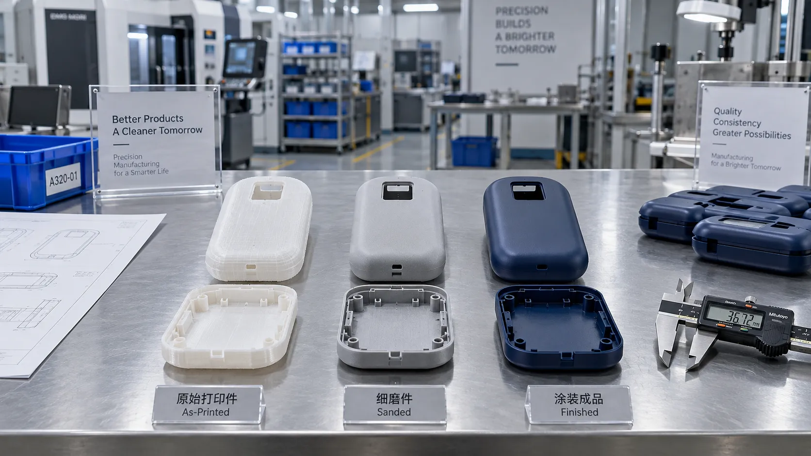
Choosing a 3D Printing Service for Consumer Products: Finish, Fit, and Cost
Compare 3d printing consumer good services by finish, fit, materials, and total cost. Learn how to choose a reliable supplier and avoid costly defects before ordering.

Which Consumer Goods Can Be 3D Printed, and What Are the Practical Limits?
Explore 3d printing consumer goods, from custom eyewear to replacement parts. Discover practical limits on materials, safety, and costs to make smarter production decisions.
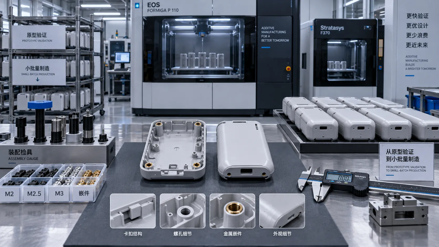
From Prototype to Small Batch: Applying 3D Printing to Consumer Goods
Explore 3d printing in consumer goods: learn how to move from prototype to small-batch production with practical guidance on materials, quality validation, and cost control.
Related News
- 00
0000-00
How to verify part consistency before choosing a 3D printing OEM - 00
0000-00
How does a rigid cryogenic transfer line handle thermal contraction? - 00
0000-00
How much does edge vision deployment cost beyond the hardware? - 00
0000-00
How does the purity of sputtering targets affect thin-film quality? - 00
0000-00
How high power laser cladding systems control substrate dilution
Dr. Hideo Tanaka
Weekly Insights
Stay ahead with our curated technology reports delivered every Monday.