
What causes slow response in engineering machinery hydraulic systems?

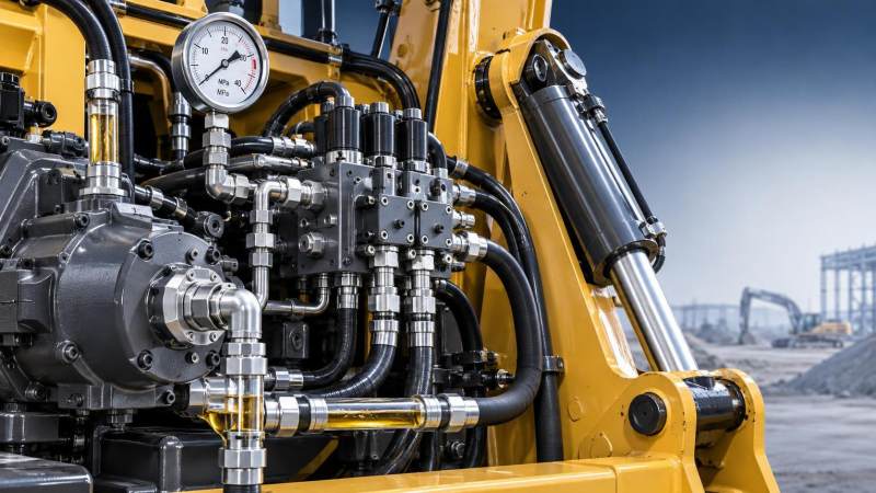
A slow hydraulic response is not a single fault. It is the visible result of insufficient flow, delayed pressure development, excessive leakage, restricted oil movement, unstable control signals, or mechanical resistance at the actuator. The practical difficulty is that several of these conditions can produce the same complaint: a boom that raises slowly, a bucket that curls reluctantly, a travel function that hesitates, or steering that feels heavy after warm-up.
The most useful starting point is to define exactly when the delay occurs. A function that is slow only when the oil is cold points toward viscosity, suction restriction, or an unsuitable fluid grade. A function that becomes slow as the machine warms points more strongly toward internal leakage, pump wear, or a pressure-control issue. If every hydraulic function is slow, the fault is likely in a common supply or control circuit. If only one cylinder or motor is slow, investigation should stay close to that function’s valve section, actuator, load-holding components, and associated lines.
Insufficient pump flow or pressure
Hydraulic actuators move according to available flow. Pressure determines whether the system can overcome the load, while flow determines how quickly the actuator can move once that load can be overcome. A system may therefore show acceptable pressure on a gauge and still respond slowly if pump delivery is inadequate.
Pump inefficiency can result from normal wear, scoring, cavitation damage, damaged internal wear plates, excessive shaft leakage, or a control mechanism that is not commanding full displacement. In variable-displacement piston pumps, the problem is not always the rotating group. A faulty compensator, load-sensing control, servo piston, or pilot signal can hold the swash plate at a low-displacement position. This is especially relevant when the machine is slow across several functions but does not show obvious noise or severe overheating.
Pressure readings must be interpreted under the correct operating conditions. Testing at engine idle, with no meaningful load, often provides little diagnostic value. Compare system pressure at the specified engine speed and during a controlled load condition, using the manufacturer’s approved test points and procedures. A pump may reach relief pressure when deadheaded but still fail to provide the required flow for combined movements. Where appropriate equipment is available, a flow test with pressure loading gives a clearer indication of pump condition than pressure testing alone.
Engine performance should be checked before condemning the hydraulic pump. Low governed speed, fuel restriction, incorrect throttle calibration, an active derate condition, or excessive accessory load can reduce pump input speed. Because pump output is directly linked to rotational speed, a machine that cannot reach rated hydraulic operating rpm can feel like it has a hydraulic fault even when the pump is serviceable.
Internal leakage that increases with temperature
Internal leakage is one of the most common explanations for sluggish hydraulic response after the machine has been operating for some time. Hydraulic oil becomes less viscous as temperature rises. A small clearance that is tolerable with cold oil can pass enough oil at operating temperature to reduce effective flow and make the system feel weak or delayed.
Leakage can occur inside pumps, main control valves, relief valves, pilot valves, cylinder piston seals, hydraulic motors, and rotary joints. It does not necessarily create an external oil leak. Instead, oil bypasses from a high-pressure area to a low-pressure or return passage, generating heat and reducing the flow available to the intended function.
A cylinder with damaged piston seals may drift under load, but drift is not the only symptom. It can also extend or retract slowly because part of the pump flow is bypassing across the piston. On double-acting cylinders, compare performance in both directions. A marked difference between extension and retraction may be related to rod-side area, load direction, counterbalance valve behavior, or unequal leakage characteristics; it should not automatically be treated as a pump issue.
In motor circuits, rising case-drain flow can indicate internal wear. Case-drain evaluation must follow the component manufacturer’s limits and test conditions because allowable values differ by motor design, speed, temperature, and displacement. Excessive case flow is important not only as a performance issue but also as a contamination risk: worn rotating components can release debris into the return circuit.
Contaminated oil and blocked filtration paths
Contamination can slow an engineering machinery hydraulic system in several different ways. Solid particles can cause spool sticking, accelerate pump wear, restrict fine orifices, and hold relief or check valves partly open. Water can reduce lubricity, promote corrosion, alter additive performance, and contribute to erratic valve behavior. Entrained air can make actuator movement soft, delayed, or jerky.
A blocked filter is not always indicated by visibly dirty oil. Filters may become restricted by fine debris, degraded seal material, oxidation products, or contamination introduced during hose replacement and component repairs. If a bypass valve opens, the machine may continue operating while unfiltered oil circulates through sensitive components. If the filter does not bypass, restriction can starve a charge circuit or create excessive return backpressure.
Do not assume that replacing a filter resolves the underlying problem. A filter element containing metallic particles, dark varnish-like deposits, rubber fragments, or unusually large quantities of contamination is evidence that requires follow-up. Cutting open an extracted filter in a clean controlled manner can help distinguish a maintenance issue from progressive component damage. The material found may point toward a deteriorating pump, motor, brake assembly, hose lining, seal, or friction component.
Suction strainers deserve particular attention after a pump failure, tank repair, or major hose work. A partially blocked suction strainer can cause low inlet pressure and cavitation without producing a dramatic external leak. The pump may emit a high-pitched whine, the oil may appear foamy, and performance may worsen as demand rises. Continuing to operate under these conditions can quickly damage a replacement pump.
Air ingress and cavitation are different faults
Air ingress and cavitation are often discussed together, but they are not identical. Air ingress occurs when outside air enters the low-pressure side of the hydraulic circuit, commonly through a loose suction hose clamp, cracked hose, damaged O-ring, poor flange seal, or leaking pump inlet fitting. Because the suction side operates below atmospheric pressure, these points may admit air without leaking oil outward.
Cavitation occurs when local pressure falls below the fluid’s vapor pressure, forming vapor cavities that collapse as pressure recovers. It can result from a restricted suction line, incorrect oil viscosity, a clogged strainer, excessive pump speed, low reservoir level, or an inlet line that is undersized or damaged. Both conditions may cause noise and unstable response, but cavitation is particularly destructive because collapsing bubbles can erode internal metal surfaces.
Check reservoir level and oil condition before dismantling major components. Look for persistent foam, a cloudy appearance, or bubbles that do not dissipate normally after shutdown. Inspect suction hoses for collapse, hardening, abrasion, and fittings that may have been disturbed during prior service. A clear temporary suction hose can sometimes reveal air movement, but any test arrangement must be rated for the application and must not introduce a new restriction or safety hazard.
Valve faults and pilot-control delays
Main control valves govern the distribution of pump flow. A spool that sticks, fails to center correctly, or does not travel fully can make one function slow even when pump performance is normal. Causes include contamination, varnish deposits, scoring, damaged centering springs, incorrect linkage adjustment, electrical command faults in electrohydraulic valves, and pilot pressure problems.
Pressure-control valves can create equally confusing symptoms. A main relief valve stuck partially open may limit available pressure for all functions. A port relief valve leaking internally may weaken only one actuator direction. A load-check valve that does not seat can allow pressure loss or function interaction. In load-sensing systems, a shuttle valve or load-sense line restriction can prevent the pump from receiving the correct demand signal, leaving pump output below what the operator requests.
Pilot circuits should not be overlooked simply because the main hydraulic pressure appears normal. Low pilot pressure, restricted pilot filters, leaking pilot hoses, faulty reducing valves, or contaminated pilot solenoids can cause delayed spool movement. The operator may describe this as “lag” rather than outright slowness: the control input is made, but the working function begins after a noticeable pause. Comparing pilot pressure before and during command can reveal whether the delay originates upstream of the main spool.
Electronic control systems add another layer. A proportional valve may be hydraulically sound but receive a limited current command because of a failed joystick sensor, damaged wiring, poor ground, controller fault, or an operating mode that intentionally limits speed. Diagnostic codes, live command values, solenoid current, and supply voltage should be checked before replacing an electrohydraulic valve. Mechanical and electrical causes can coexist, particularly after water ingress or harness damage.
Oil viscosity, temperature, and fluid compatibility
Using the wrong hydraulic fluid can alter response even when all components are in good condition. Oil that is too viscous at ambient temperature produces high suction losses and slow initial movement. Oil that is too thin at normal operating temperature increases internal leakage and can reduce lubrication margins in pumps and motors. The correct choice is not based on ISO viscosity grade alone; the machine manufacturer’s fluid specification, expected temperature range, additive requirements, and compatibility with seals and wet brake systems must all be considered.
Mixing fluids without confirming compatibility can create foaming, additive imbalance, or seal-related issues. A top-up with an unknown fluid may seem harmless, but it can complicate diagnosis when sluggish response, noise, or elevated operating temperature appears later. Oil sampling can help evaluate viscosity, water content, particle contamination, and wear debris, but the sample must be taken from a representative live zone rather than from the bottom of a stagnant container or an unclean drain point.
High oil temperature is usually a symptom as well as a contributing factor. Restricted coolers, a cooling fan fault, bypassing relief valves, excessive internal leakage, or operating conditions that keep the system near relief pressure can all elevate temperature. Once oil runs hot, leakage rises further and hydraulic response can deteriorate rapidly. The maintenance decision should focus on why heat is being generated or not rejected, rather than treating oil temperature as an isolated problem.
Mechanical resistance can mimic a hydraulic defect
Not every slow motion is caused by lost hydraulic performance. Binding pins and bushings, seized attachment pivots, damaged cylinder rods, misaligned structures, brake drag, gearbox defects, or excessive external load can require more pressure and flow than the system can provide under normal conditions. A cylinder may appear hydraulically weak when the actual restriction is mechanical.
Inspect the mechanical load path before escalating to pump replacement. Uneven movement, unusual structural noise, local heat at pivots, damaged lubrication points, or slow movement only through a certain part of the stroke may indicate binding. For travel systems, compare left and right track behavior, inspect brake release pressure where applicable, and consider whether undercarriage condition or final-drive resistance is affecting the result.
A fault-isolation sequence that avoids unnecessary parts replacement
Efficient diagnosis depends on separating common-circuit faults from function-specific faults. Start by recording the complaint under repeatable conditions: engine speed, oil temperature, selected work mode, load condition, and which functions are affected. Verify fluid level, fluid specification, visible leakage, filter indicators, engine rpm, and active diagnostic codes. These simple checks often prevent a lengthy investigation based on an incomplete symptom description.
Then determine whether the system is losing pressure, losing flow, or failing to command flow. Pressure gauges installed at the specified test ports can identify relief settings, pilot supply issues, and abnormal pressure drops. Flow measurement helps establish pump delivery and return leakage. Temperature comparison can reveal bypassing components, although surface temperature alone is not proof of a defect. A component that is unusually hot relative to adjacent circuit parts may be dissipating energy through restriction or internal leakage.
For a single slow function, compare pressure at the valve work port with pressure at the actuator, inspect pilot command to the relevant spool, and evaluate return-side restrictions or load-holding valves. For system-wide slowness, move upstream: engine speed, reservoir condition, suction path, charge pressure where fitted, pump control signal, pump output, main relief behavior, and cooler or return restrictions.
Blindly increasing relief pressure is not a repair strategy. It may mask leakage temporarily while overstressing hoses, seals, structural components, and the pump. Likewise, replacing a pump without correcting contamination, inlet restriction, or a faulty control signal can cause the new unit to fail or deliver the same disappointing response.
Slow response should be treated as a circuit-performance problem rather than a component guess. When operating temperature, affected functions, pressure behavior, flow availability, and control command are evaluated together, the fault path becomes narrower and repairs become more defensible. The goal is not merely to make the machine move faster at the end of a test; it is to restore stable response without leaving the cause of wear, heat, contamination, or pressure loss in the system.
Related News
How to verify part consistency before choosing a 3D printing OEM
Choosing a 3D printing OEM? Learn how to verify part consistency with repeat-build trials, validated inspections, and traceability checks before committing to production.
How does a rigid cryogenic transfer line handle thermal contraction?
Learn how a rigid cryogenic transfer line manages thermal contraction with bends, bellows, and guided supports. Discover key design checks for safe, reliable cryogenic performance.
How much does edge vision deployment cost beyond the hardware?
Understand edge vision deployment cost beyond hardware, from data and integration to security and support. Uncover hidden expenses and build a smarter lifecycle budget before you scale.
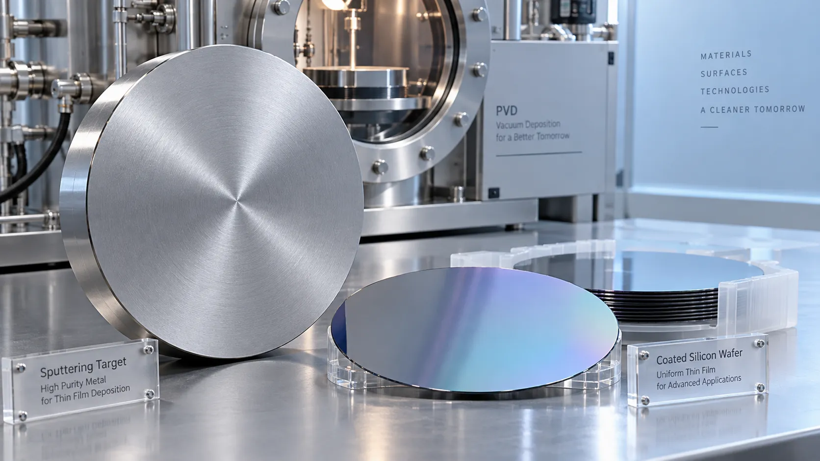
How does the purity of sputtering targets affect thin-film quality?
Discover how sputtering targets affect thin-film quality. Learn to assess purity, identify harmful impurities, and choose specifications that improve coating performance.
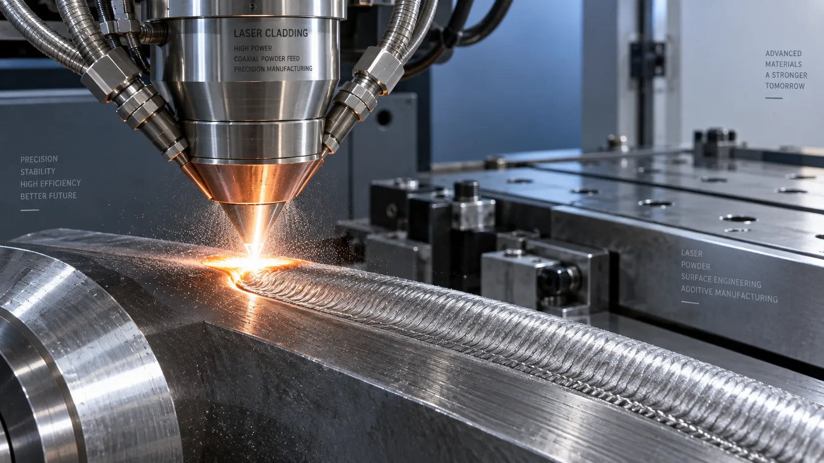
How high power laser cladding systems control substrate dilution
Discover how high power laser cladding systems control substrate dilution through beam shaping, material feed, and thermal management to deliver reliable bonds and coating performance.
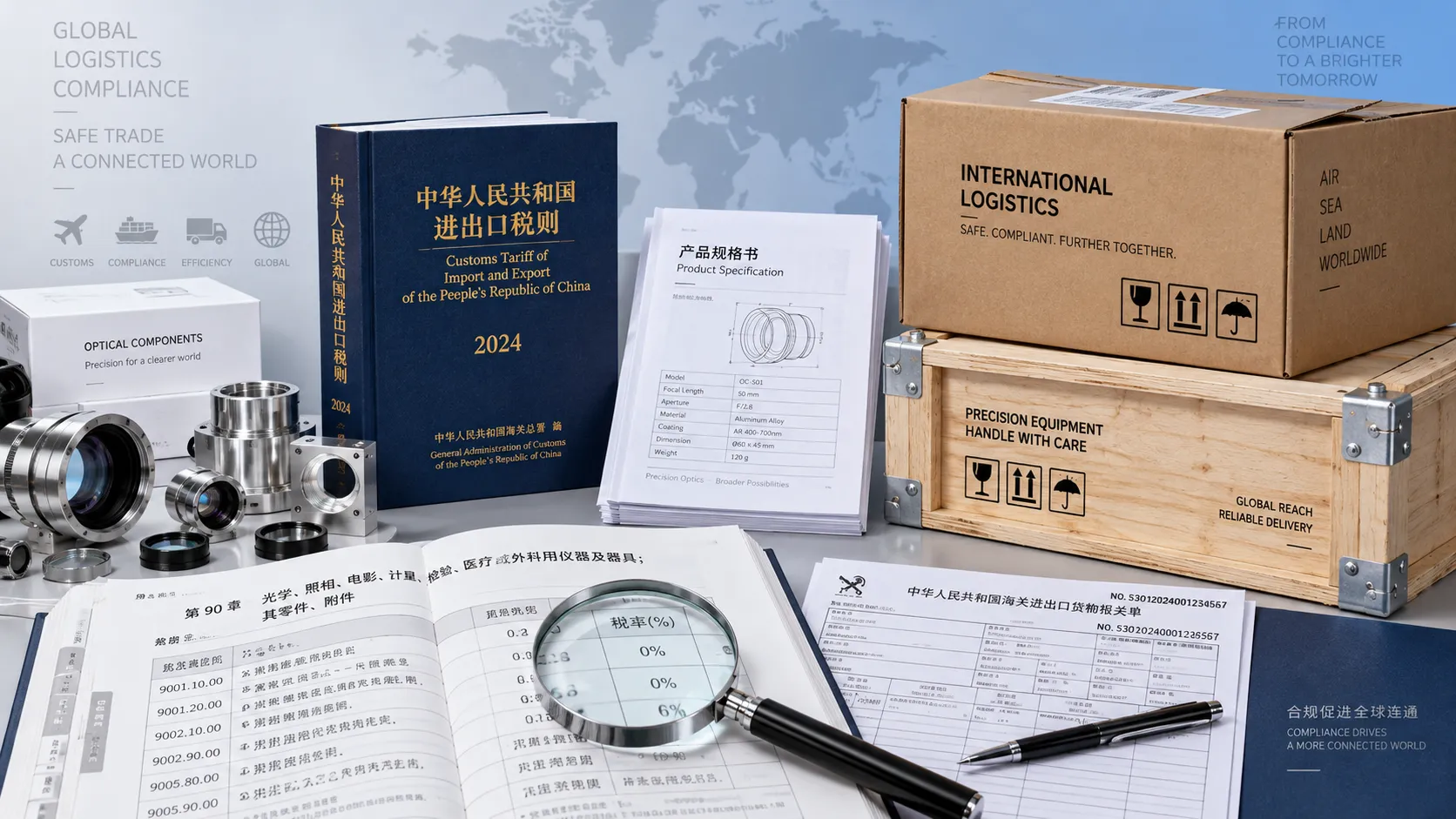
How to check HS codes for customs compliance in international logistics
Strengthen international logistics customs compliance: learn how to verify HS codes, check official tariffs, and document classifications to reduce costly shipment delays.
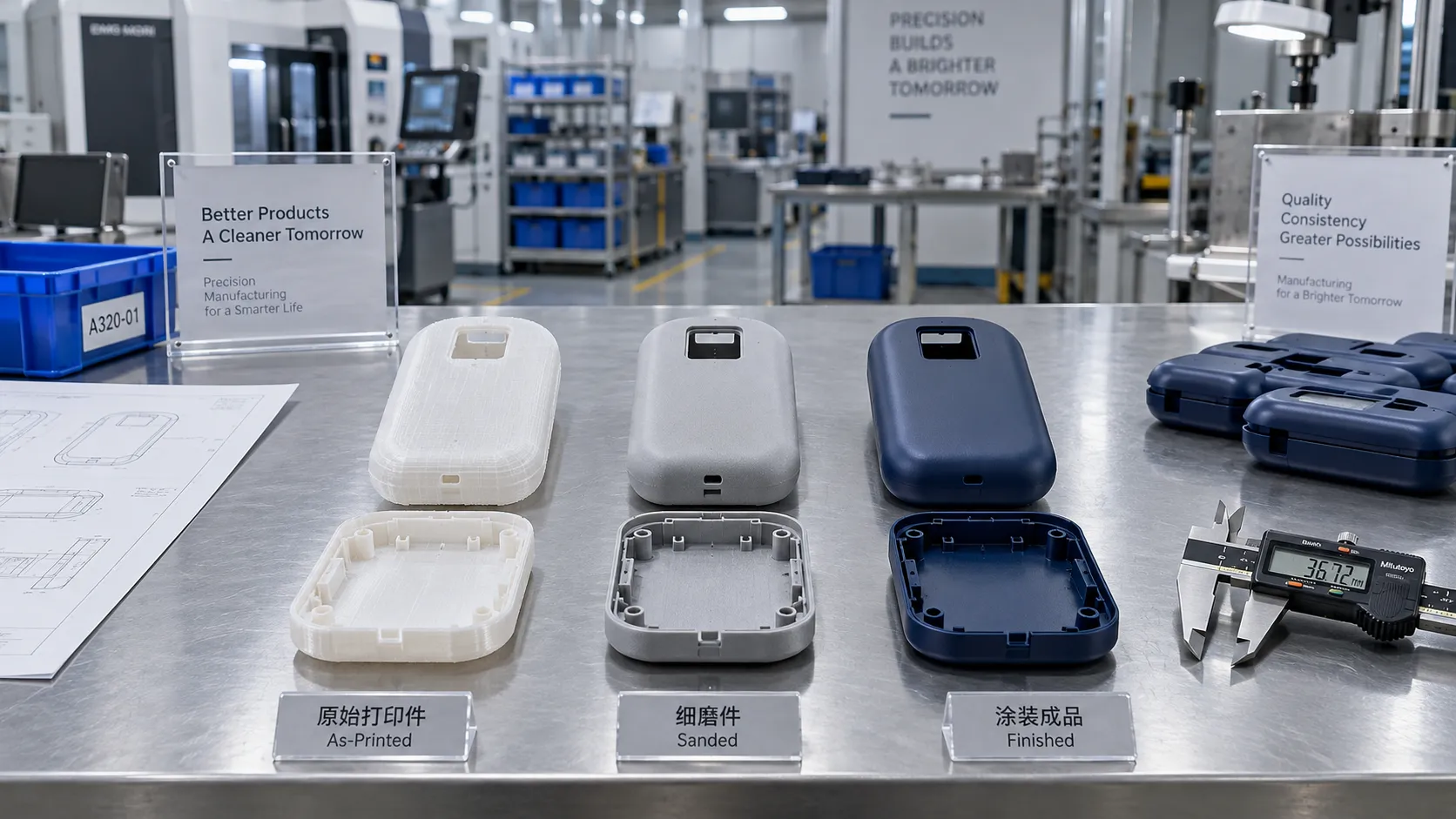
Choosing a 3D Printing Service for Consumer Products: Finish, Fit, and Cost
Compare 3d printing consumer good services by finish, fit, materials, and total cost. Learn how to choose a reliable supplier and avoid costly defects before ordering.
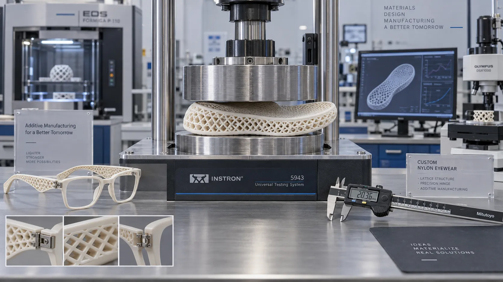
Which Consumer Goods Can Be 3D Printed, and What Are the Practical Limits?
Explore 3d printing consumer goods, from custom eyewear to replacement parts. Discover practical limits on materials, safety, and costs to make smarter production decisions.
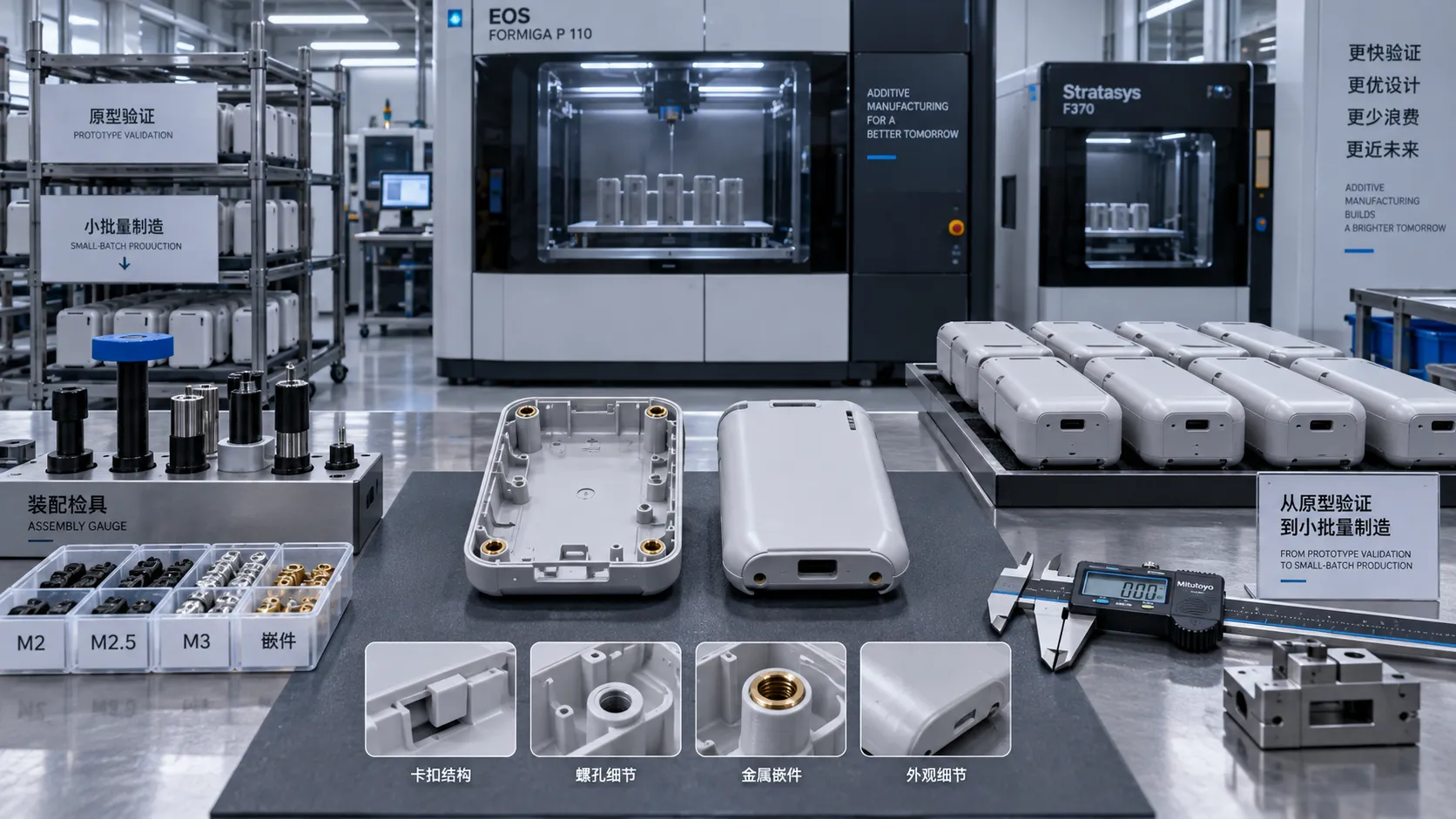
From Prototype to Small Batch: Applying 3D Printing to Consumer Goods
Explore 3d printing in consumer goods: learn how to move from prototype to small-batch production with practical guidance on materials, quality validation, and cost control.
Related News
- 00
0000-00
How to verify part consistency before choosing a 3D printing OEM - 00
0000-00
How does a rigid cryogenic transfer line handle thermal contraction? - 00
0000-00
How much does edge vision deployment cost beyond the hardware? - 00
0000-00
How does the purity of sputtering targets affect thin-film quality? - 00
0000-00
How high power laser cladding systems control substrate dilution
Dr. Hideo Tanaka
Weekly Insights
Stay ahead with our curated technology reports delivered every Monday.